3D-Printed Glare Reducing Camera Mount
Massachusetts Materials Technologies
Overview
During my time with Massachusetts Materials Technologies, I created a 3D-Printed camera mount that eliminated glare on a reflective surface for pipe seam imaging.
In the field, the company would perform an acid etch of a metal pipeline and take a picture of it in order to help determine the type of weld. The photos were poor quality and rarely provided the information required, and I was tasked with fixing this problem.
Design Process
Flow of design process, showing the initial prototype (top left) to the final product (bottom right). At each step, the major changes are noted.
Prototype 1
In the beginning, the R&D team suggested using a black plastic with holes in order to mimic a camera hood, and the field technician would cover different holes depending on the current ambient light to create the best picture. As seen to the right, this had limited results, as the black plastic blocked far too much light.
Prototype 2
The first idea to fix this was to widen the holes to increase the light control, as well as add a curve to the bottom to get rid of the light leak due to the pipes having a diameter of anywhere from 3-36 inches. This worked decently, but the results were nowhere near where they needed to be in order to take consistent, report quality photos.
Prototype 3
During a weekly R&D meeting, I had the idea of changing the 3D-printing filament to either a translucent or white color, in order to disperse the ambient light and in turn reducing glare. I knew that PLA came in a multitude of variations, but I was unsure of whether a transparent or translucent would allow enough light in. The team liked the idea and allowed me to pursue it, and as seen in the image it worked very well. I also changed the 4 large holes to a row of small ones to try to disperse the light even further, but this proved to be unnecessary.
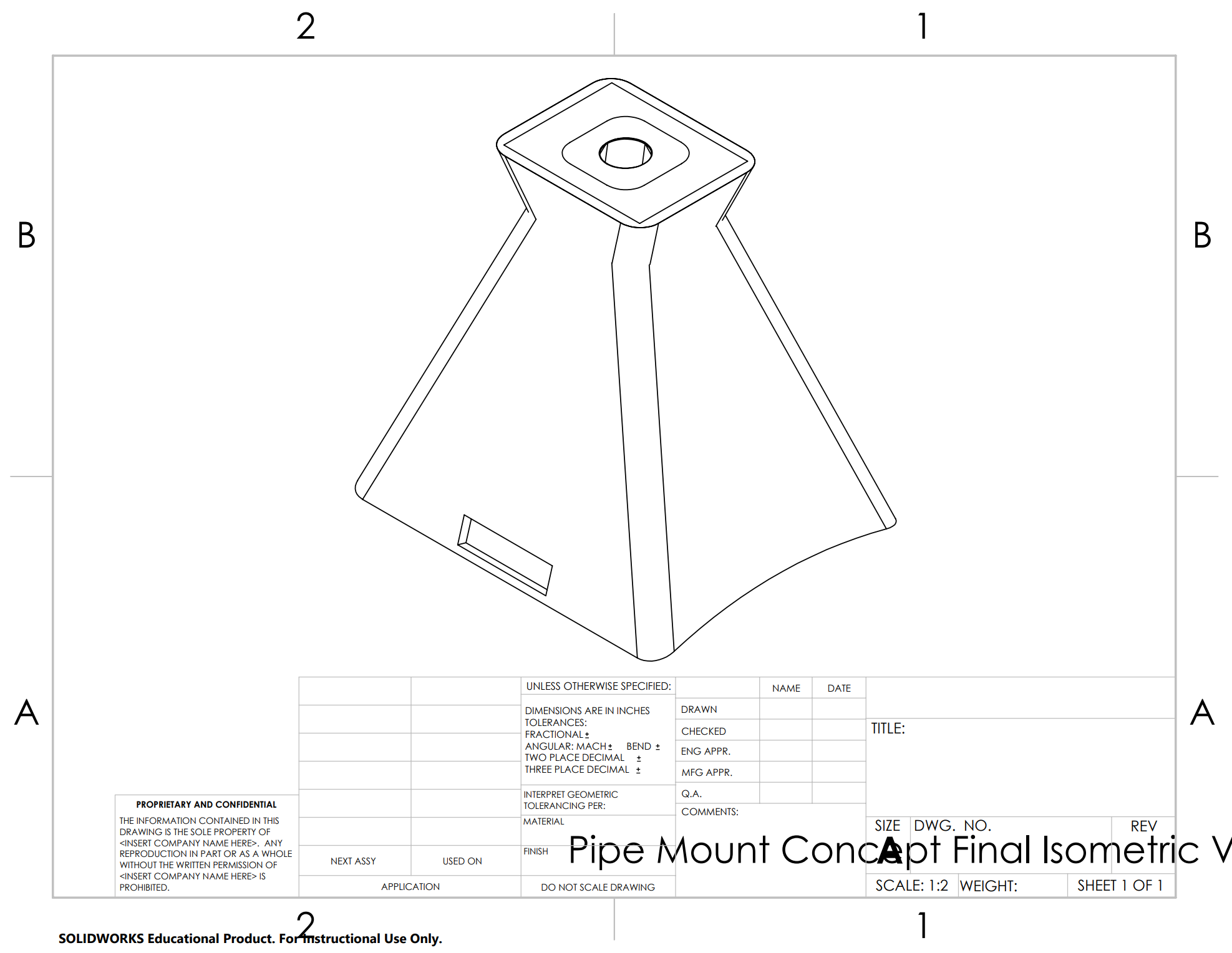
After this, the design path was much more clear, and my goals shifted from optics to user interface and optimization. I increased the height once again in order to maximize the field of view for a standard phone camera. I also added small markers to show the center of the field of view, and I made sure to keep the interior edges rounded as to not create sharp lines in the reflection. Finally, the platform to support the phone camera was added, and cutouts for magnets to allow the mount to stick to the metal pipes were also added.
There were several other optimizations done that were not mentioned. For example, I changed the design 4-5 times in one week in order to remove a spot of the cone that would appear blurry in images. Having my own 3D-printer made this process much easier, as I was able to re-design the mount in the evening, print it overnight, and test it in the office the next day. Additionally, I designed the part with 3D-printing in mind, and ensured there is no need for rafting or supports.
Final Product and Results
Before image of pipe seam vs. after, with the use of the pipe mount. Note the clear bond line (marked with sharpie) and darkened heat affected zone in the after image.
As seen in the above images, the final product vastly improved the images of the etched pipe bond line, and everyone on the R&D and field teams agreed that my project was a success. In total, the project was in the background for roughly 4 months, wrapping up near the end of June. The company had me print a total of 10 mounts for them to use over the next few years, and I left behind the SolidWorks and STL files for ease in re-creation.
CAD of final design
Since then, other field technicians from other companies have noticed the product in the field, and I have printed an extra eight mounts for MMT to sell to these companies. Because of this, I am currently working with MMT to patent the product. I have also produced roughly twenty more mounts for MMT to use as it grows as a company.
During this project, I developed my 3D-Printing, CAD Modeling, and Material Selection skills.


